
Denso 4 Wire O2 Sensor Wiring Diagram Wiring Diagram Schematic
In summary, a 4-wire O2 sensor consists of a sensor element, heater, wiring and connector, and a protective housing. These components work together to accurately measure the oxygen content in the exhaust gases and provide vital feedback to the vehicle's engine management system. Wiring Diagram for a 4 Wire 02 Sensor

Denso 4 Wire O2 Sensor Wiring Diagram Wiring Diagram Schematic
The intricate dance of wires within a vehicle's engine might seem bewildering, but fear not! Unveiling the mysterious denso 4-wire O2 sensor wiring diagram sheds light on this entangled labyrinth. Delving into its intricacies, this article unveils the secrets behind the seamless functioning of this vital automotive component. So, gear up and embark on this voyage of discovery!

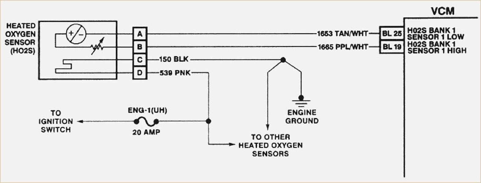
Gm O2 Sensor Wiring Diagram
Part Number Search Cross Reference information is provided as a guide only. Please refer to the "Applications" lookup tabs for more detail. Materials and designs will differ among brands, so plugs are not exactly alike. Always check with your OE service manual for proper installation and settings.
O2 sensor wiring help IH8MUD Forum
Testing an O2 sensor with a multimeter is a simple process that can be done in a few steps. First, switch the multimeter to the ohmmeter mode and back pro be the heater wires. Then, connect the red lead of the multimeter to the heater hot wire and the black lead of the multimeter to the heater ground wire.

Denso 4 Wire O2 Sensor Wiring Diagram Easy Wiring
These four wires are the positive wire, negative wire, heating wire, and signal wire. Firstly, the positive wire and negative wire, typically both white in color, connect to the oxygen sensor's heating coil power source and ground wire. The role of these two wires is to supply power to the oxygen sensor's heating element, enabling it to quickly.

Gm O2 Sensor Wiring
An oxygen sensor, also known as an O2 sensor, is an electronic device that measures the oxygen levels in a vehicle's exhaust system. It plays a crucial role in monitoring and controlling the air-fuel mixture in the engine, ensuring optimal combustion and reducing harmful emissions.

Hyundai O2 Sensor Wiring Diagram
O2 Sensor & Wiring DiagramsAmazon Printed Bookshttps://www.createspace.com/3623928Amazon Kindle Editionhttp://www.amazon.com/Automotive-Electronic-Diagnostic.

Corolla P0138 trouble codeRicks Gratis Auto Repair Råd Ricks Gratis
A typical Denso oxygen sensor wiring harness consists of four wires - two white wires, one black wire, and one gray wire. The white wires are for the sensor's heater circuit, which helps the sensor reach its operating temperature quickly.
Chevy Cruze O2 Sensor Wiring Diagram
Oxygen sensors, also known as Lambda sensors or O2 sensors among some vehicle manufacturers, are among the most sensitive and critical components on your car's engine. Earlier fuel injection systems employed one oxygen sensor in the exhaust system to maintain closed-loop air/fuel mixture control. However, today's engines may use as many as.

2003 Toyota Camry Oxygen Sensor Wiring Diagram Wiring Diagram and
How to Install a Universal 4 Wire Oxygen Sensor Global Automotive of Miami, Inc. 557 subscribers Subscribe Subscribed 22K views 6 years ago This video briefly explains how to install a universal.
Reyhan Blog Bosch Oxygen Sensor Wiring Colors
Removal Instructions Exhaust system should be at ambient temperature. Disconnect the oxygen sensor wire at the vehicle wire harness. Note the routing of the oxygen sensor wire. Remove the oxygen sensor with the appropriate tool(s). (Ratchet & socket or wrench) Check the threads on the exhaust manifold/pipe to make sure they are not damaged.
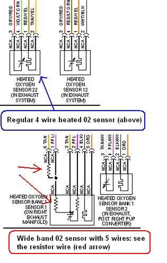
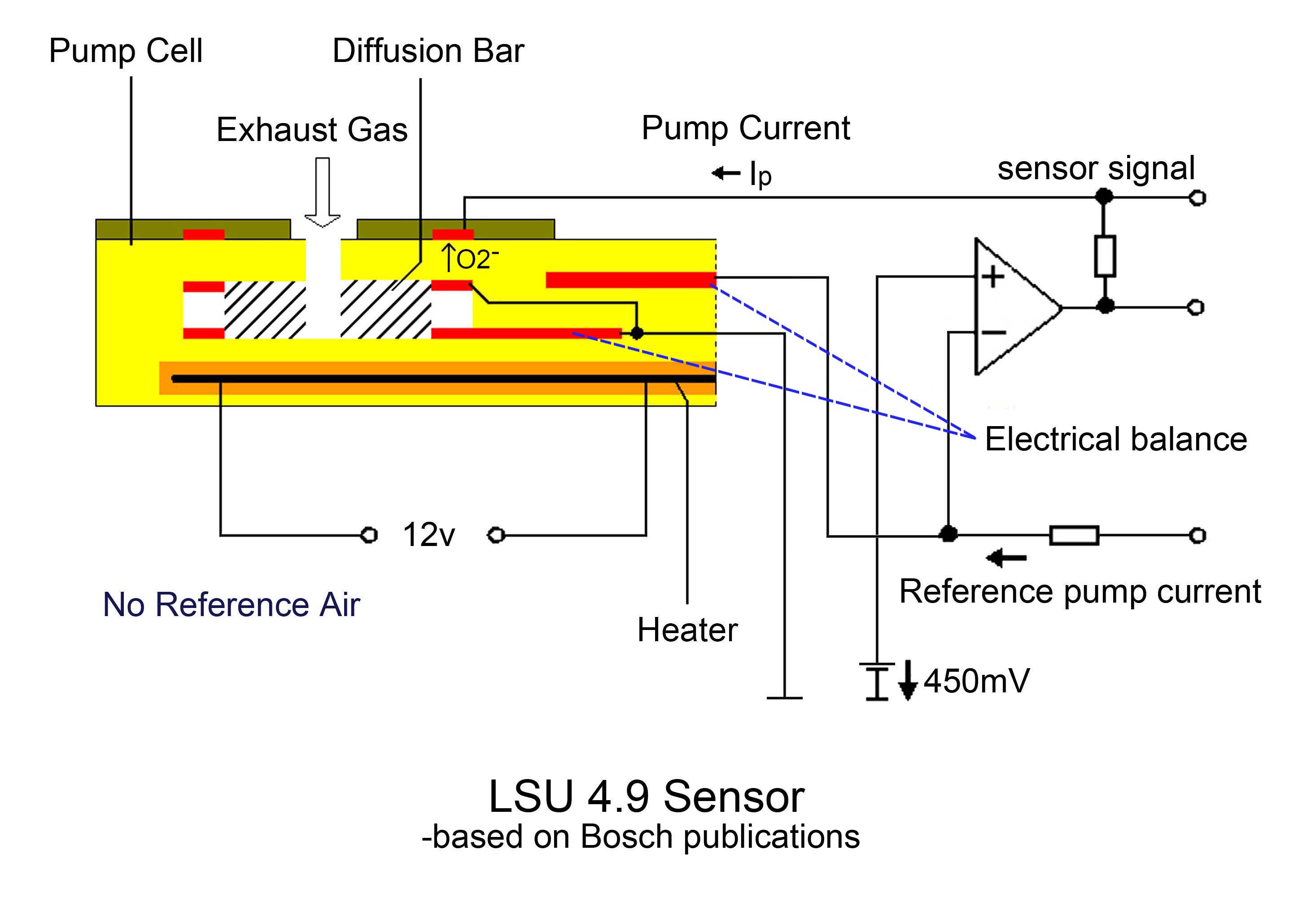
Wideband O2 Sensor Wiring Diagram
It is the function of the O2 sensors (oxygen sensor) to give accurate information to your car computer to avoid driving issues, emission failures, and increased fuel consumption. This makes the oxygen sensor one of the most vital sensors in a vehicle. Sometimes it is known as the "O2" sensor.
bosch o2 sensor wiring diagram
Wiring a 4 wire O2 sensor is surprisingly simple - there are two heater wires, a signal, and an earth wire to connect to the back of the power plug. You can solder the wires, or use connector pieces if they're provided with the replacement set. 4 Wire O2 Sensor Diagram Before we dive into the how-to, let's review what we're working with.

O2 Sensor Wiring Diagram
The O2 sensor signal gives an indication of oxygen content sensed by the probe by sending an induced voltage that corresponds to the level of oxygen detected. However, this does require the sensor to be heated up to operating temperature. Necessary precaution must be taken.

Understanding Chevy 4 Wire O2 Sensor Wiring Diagram WIREGRAM
The oxygen sensor generates a voltage signal that varies with the amount of oxygen in the exhaust gas. This signal helps the ECU make adjustments to the air-fuel mixture for optimal engine performance. When wiring a Denso 4 wire o2 sensor, it is essential to follow the manufacturer's instructions and consult the vehicle's wiring diagram.
[8+] Denso O2 Sensor Wiring Diagram, UNIVERSAL LAMBDA SENSOR (OXYGEN
The 4-wire oxygen sensor, also known as the Lambda sensor, measures the oxygen content in the exhaust gases of an internal combustion engine. It provides valuable data to the engine control unit (ECU), allowing it to adjust the air-fuel mixture for optimal combustion. The sensor has four wires that connect to different components, each playing.
